|
This project includes some precision operational amplifiers LM108 with good thermal stability, low offset and low bias currents. These components are ideals for instrumentation applications.
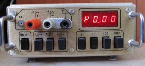
The fourth digit module from LED
display has been modified to be able to display "+", "-" and "~" signs. The modifications have been
made by breaking apart and changing
the plastic mask windows. Same module also shows "u" in voltmeter mode, "i" in amperemeter mode and "r" in ohmmeter mode (figure 8).
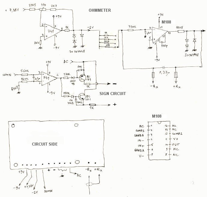
Plus (+) and minus (-) LEDs from fourth module are driven by "sign circuit". (figure 10)
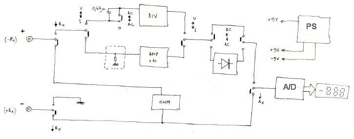
There is a voltage follower at A/D converter input, made with M108 operational amplifier (figure 7).
It is used as impedance adapter between voltage divider and A/D converter. CA3162 has a multiplexed BCD output.
For driving the LED display is provided a 4511 - BCD to 7 segment decoder.
"Sign circuit" is built with general-purpose operational amplifier A741, used here as a voltage comparator.
It has resistors of different values at the inputs (pin 2 and 3) to compensate its voltage/current input offset.
There is another A741 in the module used to create -1 V reference voltage for ohmmeter.
Ohmmeter is built with an inverting amplifier (figure 10) starting from a reference voltage at input.
Output voltage is
in proportional relationship with the measured resistor.
A non-inverting amplifier with a fixed gain of 10 is used as amperemeter (figure 11).
It has the role to allow the use of shunts with low values when measuring currents.
The following appropriate actions have been taken to improve the accuracy of the instruments
(as stated in specification):
-selection of operational amplifiers with lowest input voltage/current offset to be used in project.
-use of metal film resistors with low tolerance on all modules from in the measurement chain
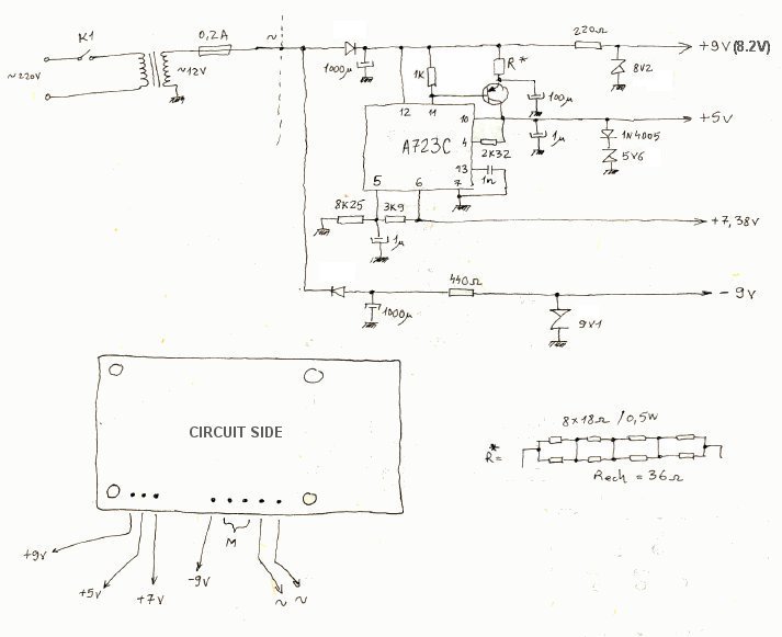
-power supply for all modules and reference voltage for ohmmeter made with precision
voltage regulator LM723
-resistors from divider and other critical places have been calibrated to precise values
by selection or by using serial/parallel combinations.
Disclaimer: The information on this web site is provided "AS IS", without warranty of any kind.
The author has made the best efforts to ensure the design and the information provided are reliable.
Under no circumstances shall the author be liable for any direct, indirect, incidental, special
or consequential loss, damage, expense or injury incurred or suffered which is claimed
to resulted from use of this site, even if expressly advised of the possibility of
such loss, damage, expense or injury,
including, without limitation, any fault, error, omission, interruption or delay with respect thereto.
Links:
[1] - Wikipedia - Multimeter:
http://en.wikipedia.org/wiki/Multimeter
[2] - A/D Converter, 3-Digit Display:
CA3162
[3] - Precision operational amplifiers: LM108
|