|
|
Automation with Logo Controller
|
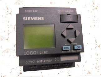
LOGO! is a PLC with simple installation, easy wiring and user-friendly programming interface. It consists of LOGO! Basic and LOGO! Expansion modules. Logo! is a mini PLC for smaller projects that lets you implement functions such as time-delay switches, time relays, counters and auxiliary relays. It is also available a Siemens LOGO Starter Kit PLC Programming for beginners. I started a demo multipurpose automation project in 2008 with Logo controller. It can be used for learning purpose, you can implement many applications with it, for example a driver for a hydrophore - storing drinking water. The system presented here is a demo unit. It was built to drive two electric motors, max 10 kW, 400 VAC, three-phase. I made several versions in 2008-2009 with or without analog modules and current transformers for evaluation, here you can find documentation for the final built.
|

Figure 1
Automation |

Figure 2
Board |
Figure 3
Enclosure |
|
Specification:
- Controller Logo used
- with display and keys
- power supply 24 VDC
- 8 digital inputs 24 VDC, of which 2 can be used as analog (0 to 10 V)
- 4 digital outputs 24 VDC / 0.3 A
- One expansion module:
- 4 digital inputs DC 12/24 V
- 4 relay outputs 24 VDC / max 10 A
- Two fuse switch disconnectors:
- 690 V rated
- 160 A rated
- equipped with 100 A fuses
- Two power contactors:
- 37 kW rated at 400 V, AC-3
- equipped with aux. contacts
- equipped with surge suppressors
- Two thermal overload protection relays
- adjustable overload release 57...75 A
- max operating voltage 1000 V, AC-3
- Internal power supply
- input 230 VAC
- output 24 VDC/ 1 A
- Miniature circuit breakers, auxiliary relays etc
(the current transformers shown in figures 1 and 2 have been removed in final built)
|

Figure 4
Schematic 1 |
Figure 5
Schematic 2 |
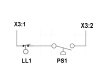
Figure 6
Switches |
|
Figures 4 and 5 contain the schematic diagrams of the automation. In figure 6 is the wiring diagram in case of use as hydrophore - storing drinking water. There are two sensors. First is a pressure sensor for water presence, mounted in upstream pipe before the pumps. If there is no water, the pumps must not start. The second sensor is a liquid level switch mounted in the water storage reservoir for maximum level. When this switch is actuated, the pumps must stop. On the front of the enclosure, there is a selector switch for manual/automatic functions and push buttons with lamps for manual start/stop of both motors.
|
|
Warning: Without any doubt, this project is not for amateurs and hobbyists. The components and system described in this documentation may be built, installed and operated only by personnel qualified for these specific tasks. Qualified personnel are those who, based on their training and experience, are capable of identifying risks and avoiding potential hazards when working with these products/systems. It is mandatory to follow all the applicable safety regulations for work in 400 V voltage environments. This system was built for learning and evaluation purpose only. For use in a real application, you may have to change some components and the system must include additional components and functions such as emergency stop, differential protection relays etc.
Disclaimer: The information on this web site is provided "AS IS", without warranty of any kind.
The author has made the best efforts to ensure the design and the information provided are reliable.
Under no circumstances shall the author be liable for any direct, indirect, incidental, special
or consequential loss, damage, expense or injury incurred or suffered which is claimed
to resulted from use of this site, even if expressly advised of the possibility of
such loss, damage, expense or injury,
including, without limitation, any fault, error, omission, interruption or delay with respect thereto.
Links:
[1] - Logo manual
|
|
|