|
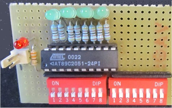
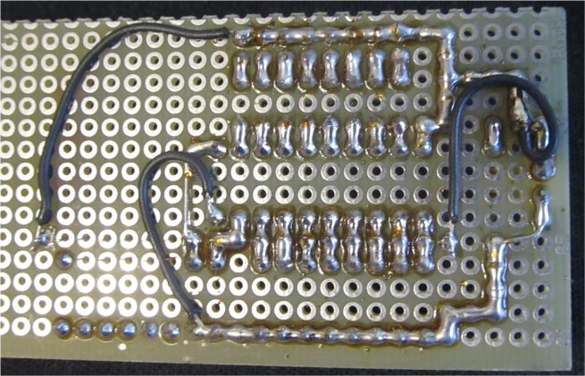
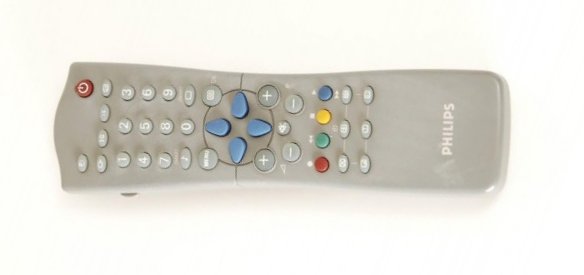
Figures 1 and 2 shows a test PCB for verifying that microcontroller was programmed correctly. Figure 4 shows the IR receiver. The schematic diagram of the prototype is in figure 5. In figure 6 is an image of the IR remote control I have used for testing (Philips RC2543/01). Figure 7 shows the program I have used to identify the codes of the remote control. You must know that every IR remote control have a set of standard codes, but also there are specific codes that belongs to that IR RC. The program was made for my development system [1]. The codes are sent on serial communication and displayed on PC by monitor program. Figure 8 shows the codes identified by me for that specific remote control. After you establish what keys and codes you will use from IR remote control, you can add to the program the correspondence between codes and physical outputs. Then you can burn the program to 89C series microcontroller.
Warning: SFH-5110-36 [4] is not a simple IR sensor. It contains all is necessary to decode IR remote control pulses: photodiode, preamplifier, automatic gain control, bandpass filter and demodulator for 36 kHz. If you use another type of remote control unit, it is possible to not have the same communication protocol, so you must use another IR receiver.
Disclaimer: The information on this web site is provided "AS IS", without warranty of any kind.
The author has made the best efforts to ensure the design and the information provided are reliable.
Under no circumstances shall the author be liable for any direct, indirect, incidental, special
or consequential loss, damage, expense or injury incurred or suffered which is claimed
to resulted from use of this site, even if expressly advised of the possibility of
such loss, damage, expense or injury,
including, without limitation, any fault, error, omission, interruption or delay with respect thereto.
Links:
[1] -
8051 development system
[2] - AT89C2051 datasheet
[3] - Atmel microcontrollers programmer
[4] - SFH5110 datasheet
|