|
|

|
|

|
|
|
Sine - Cosine generator
|
Sine and cosine functions are sinusoids of different phases. The phase difference is 90°. These waves are the fundamental
building blocks of communications and signal processing (modulation, demodulation, FFT spectral analysis). There are many methods
to generate sine-cosine waves. An electro-mechanical sine-cosine generator is the resolver, for example.
A motor rotates a cylinder about central axis. Two non-contact displacement sensing devices are placed ninety degrees apart,
equal distances from the axis of rotation of the cylinder and short distances above the surface of cylinder.
Each of these sensing devices produces an electrical signal proportional to the distance that it is away from the cylinder.
Consequently, as the cylinder is rotated, the outputs from the two sensing devices are the sine and cosine functions.
A resolver is measuring degrees of rotation. It is considered an analog device.
|
|
|
There are also digital resolvers called rotary encoders or shaft encoders. These devices convert angular
position or motion to a digital code.
|
|
In 1990, I started a project to simulate an electro-mechanical analog resolver
with electronic circuits. Later, my project was embedded in a radar simulator.
At that time, I had difficulties in finding microcontrollers and FPGAs so I had
to use standard Logic ICs and EPROM memories to store digital code.
Specification:
- Output: two sinusoids with phases at 90°
- Output signal range: ± 16-20 V (adjustable)
- Output current: max 20 mA
- Voltage accuracy: ± 0.02 V (11 bit resolution)
- Period: 10 sec
- Period accuracy: better than ± 0.005 sec
- Power supplies: +5 V / 1 A, ± 15 V / 100 mA, ± 24 V / 100 mA
|

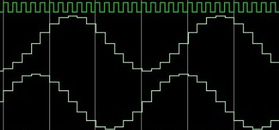
Figure 1
SinCos Gen |
Figure 2
Counter |
Figure 3
Amplifier |
|
Figure 2 contains schematic diagram of the counter, starting from 18.432 MHz oscillator.
In the circuit follows three divide-by-ten counters - U3, U4 and U5. At the output of U3,
there is an 18.432 kHz signal. U2 is a divide-by-nine counter and U1 is a divide-by-five counter.
The 10 seconds interval of a rotation is divided into 4096
parts with a 12 bit BCD counter made with U19, U20 and U21.
Figure 1 shows the generator made with three 2716 EPROMs addressed from the 12 bit BCD counter and
two 8 bit D/A converters on each channel (sine and cosine) with outputs in parallel connection. The first D/A converter uses 8 bit
and the second only 3 bit (11 bit total resolution). Converters are followed by precision operational amplifiers.
Figure 3 contains schematic diagram of the final amplifiers with fixed gain=2. I made these amplifiers
with precision op-amps and discrete components, instead of using dedicated ICs,
to obtain the required precision. The final transistors must be mounted on heatsink.
|
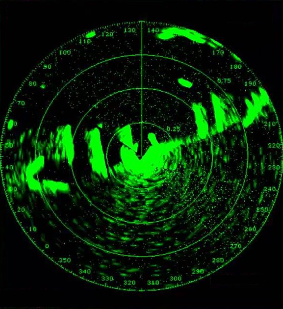
Figure 4
Radar
screen |

Figure 5
Program |
|
Figures 4 shows an example of radar screen image. Figure 5 shows an example
of program to calculate the content of EPROM memories.
|
|
Note: This project is a prototype. Is far from being an optimum design.
It was made with scrap components I have at that moment. PCB for prototype was made by me manually (nail polish,
ferric chloride, baking soda).
Disclaimer: The information on this web site is provided "AS IS", without warranty of any kind.
The author has made the best efforts to ensure the design and the information provided are reliable.
Under no circumstances shall the author be liable for any direct, indirect, incidental, special
or consequential loss, damage, expense or injury incurred or suffered which is claimed
to resulted from use of this site, even if expressly advised of the possibility of
such loss, damage, expense or injury,
including, without limitation, any fault, error, omission, interruption or delay with respect thereto.
Links:
[1] - Encyclopedia of Electronic Circuits [R. Graf, W. Sheets], 1985
[2] - DAC08 datasheet
[3] - Radar Handbook [Merrill I. Skolnik]
[4] - Radarul romanesc. O Istorie vie [Anton Muraru], 2019 (page 136)
|
|
|

|
|

|
|