Automotive electronic components
|
Here you can find a short presentation written by me in 1997 (in Romanian language) for most used automotive integrated circuits manufactured by Temic Telefunken, these are still very common in European and American cars of the 2020s.
TEMIC (TElefunken MICroelectronics) was originated from the semiconductor division of AEG, which itself was formed from the merger of Telefunken and Siemens. The integrated circuit (IC) portion of TEMIC was sold to Atmel Corporation in 1998, which was later absorbed into Atmel's core business. In 1998, AEG sold the discrete and power electronics portions of TEMIC to Vishay. Atmel was acquired by Microchip Technology in 2016, meaning TEMIC's product lines and technologies are now part of Microchip's extensive portfolio.
Specific to the automotive components is the temperature range from -40°C to +125°C they need to function. Other typical domains are Commercial: 0 to 70 °C (32 to 158 °F), Industrial: −40 to 85 °C (−40 to 185 °F), Military: −55 to 125 °C (−67 to 257 °F).
|
|
Next step in automotive industry was OBD (On-Board Diagnostics) interface. OBD2 is your vehicle's built-in self-diagnostic system. It is a standardized protocol that allows extraction of diagnostic trouble codes (DTCs) and real-time data via the OBD2 connector. Almost all newer non-electric cars support OBD2 and most run on CAN bus. For older cars, note that even if a 16 pin OBD2 connector is present, it may still not support OBD2. It was introduced in 2003: Required in EU also for diesel cars (EOBD). OBD2 has originally been designed for the purpose of emissions control/testing. Almost none of the modern EVs support any of the standard OBD2 requests. Instead, most of them utilize OEM-specific UDS communication. Generally, this makes it impossible to decode data from these electric vehicles, except for cases where the decoding rules have been reverse engineered.
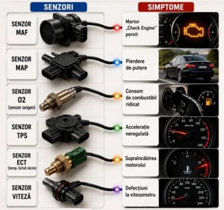
I've tested in 2009 an USB adaptor called ELM327 OBD2 Scanner used for PEUGEOT, to check if the sensors are working well. DTC stands for diagnostic trouble code, also known as a DTC engine code, engine fault code, or check engine light code. These codes are usually five characters long. DTC codes are typically one letter followed by four numbers. Each DTC is standardized, relates to a particular vehicle part and can be read from OBD port.
|
 Figure 1
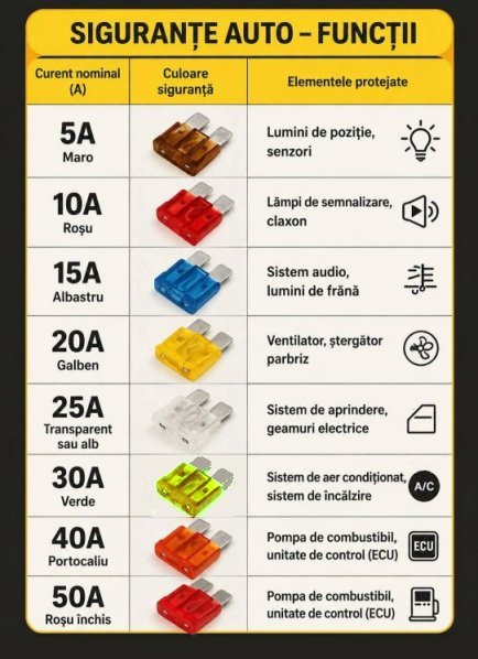
Fuse |
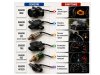 Figure 2
Sensor 1 |
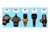 Figure 3
Sensor 2 |
|
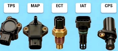
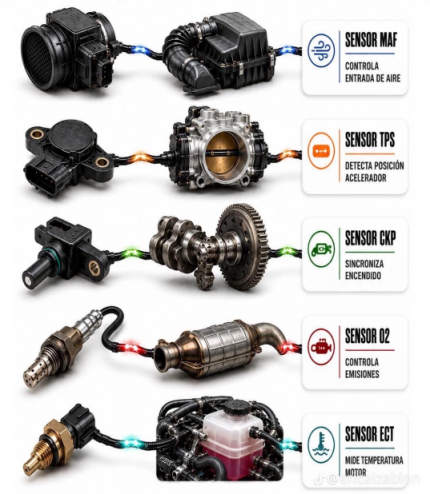
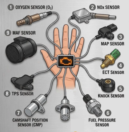
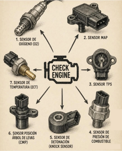
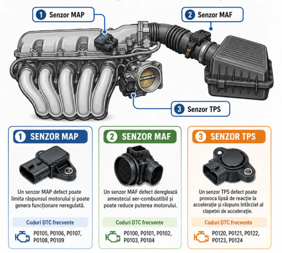
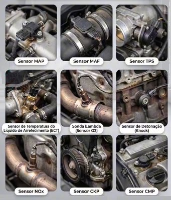
TPS throttle position sensor is used to monitor the throttle body valve position for the ECU of an engine. The sensor is usually located on the butterfly spindle/shaft, so that it can directly monitor the position of the throttle. The output is a voltage, 0.5 V for closed position and 4.5 V for opened position.
MAP sensor produces an output voltage between 0 and 5 volts, depending on the pressure. It is used to calculate fuel injection for optimal air-fuel ratio by continuously monitoring intake manifold pressure information.
ECT means engine coolant temperature sensor and it is a RTD thermoresistance typical between 500 and 1500 Ohm.
IAT is intake air temperature sensor, measures the temperature of the air charge in the intake manifold and it is a RTD thermoresistance typical between 1000 and 3000 Ohm.
MAF is mass air flow sensor and measures the amount of air entering the engine in grams per second, so the computer (ECU) can calculate the precise amount of fuel needed for optimal combustion. Typical output of this sensor is 0.5 V to 5.0 V.
CPS means camshaft position sensor, it monitors the rotational speed and position of the crankshaft and produces pulses. There are many tipes of CPS. The output of a Hall-effect camshaft position sensor is a digital signal (a square wave). A traditional magnetic sensor (often called a reluctor or inductive sensor) does not output a digital signal. Instead, it generates its own AC voltage (a sine wave) using a permanent magnet and a wire coil. Inductive sensor does not require an external power supply to produce that signal. To quickly identify which type of sensor your vehicle uses, check the number of wires in the connector: Hall-Effect sensor typically has 3 wires (a voltage supply, a ground, and a signal wire). Magnetic (Inductive) sensor typically has only 2 wires (a signal and a ground / return). Reed relay sensor and Delco sensor has a contact open / closed output.
|
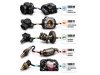 Figure 4
Sensor 3 |
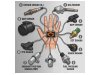 Figure 5
Sensor 4 |
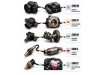 Figure 6
Sensor 5 |
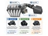 Figure 7
Sensor 6 |
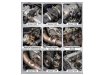 Figure 8
Sensor 7 |
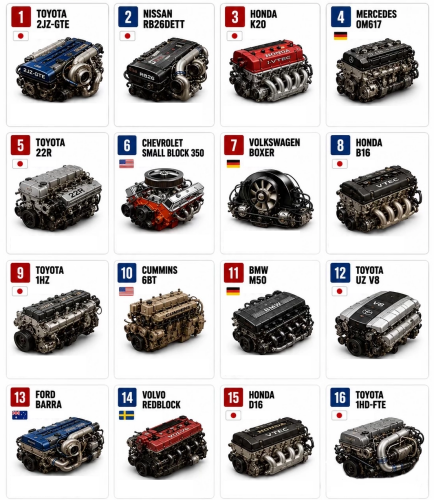
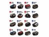 Figure 9
Engines |
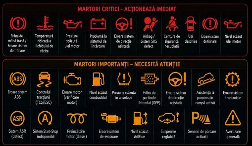
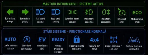
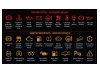 Figure 10
Dahboard 1 |
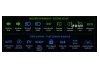 Figure 11
Dashboard 2 |
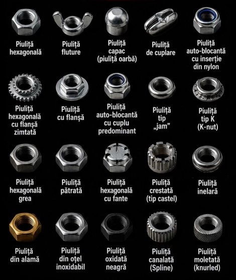
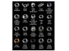 Figure 12
Nuts |
|
Disclaimer: The information on this web site is provided "AS IS", without warranty of any kind.
The author has made the best efforts to ensure the design and the information provided are reliable.
Under no circumstances shall the author be liable for any direct, indirect, incidental, special
or consequential loss, damage, expense or injury incurred or suffered which is claimed
to resulted from use of this site, even if expressly advised of the possibility of
such loss, damage, expense or injury,
including, without limitation, any fault, error, omission, interruption or delay with respect thereto.
Links:
[1] - DTC codes list
[2] - Dashboard Alarms
[3] - http://www.atmel.com/
|
|